
Product menu
- Valves - General
- Ball Valves
- Actuators
- Flanges
- Gaskets plus Seals
- Hoses
- Types of Packings
- Pipe Expansion Joints
- Pipe Fittings plus misc
- Valve End Connections
Services menu
- Hydraulic Ram and Hose Repairs
- Instrumentation
- Stock - Refurbished
- Valves - Overhaul
- Valves - Repairs
- Control Valve Spares
- Site Services Offered
Extras menu
Actuators
Please click HERE for general information on Actuators
We are able to offer a comprehensive range of Actuators and associated equipment to meet all application requirements
For all order enquiries please contact us on: +44 (0) 208 305 0792 or email: info@stoneleigh-eng.com
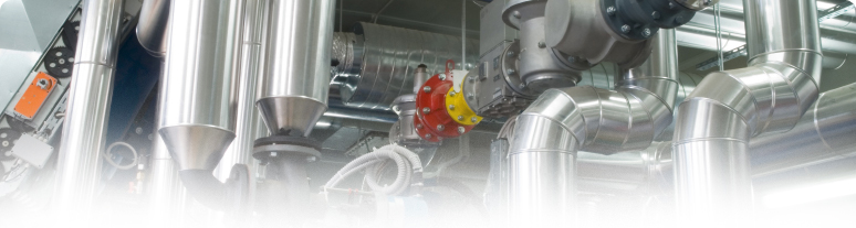
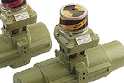
Actuators - pneumatic, hydraulic or electric
Actuators are employeed for the automation of industrial valves and uterlized in many kinds of technical process plants. They are used in wastewater treatment plants, power plants and refineries. They play a significant part in automating process control. The valves to be automated vary both in design and dimension. The diameters of the valves range from a few inches to a few metres.
Subject to their type of supply, the actuators may be classified as pneumatic, hydraulic, or electric actuators.
Please contact us with your requirements
Classification of actuators according to their movement
Movement details the distance the closing element within the valve is required to travel to completely open or close that valve. Typical closing elements include butterfly, globe or gate valve discs. These three closing elements stand for the three basic movements required for covering the travel. The butterfly valve disc is operated by a 90deg swivel movement from end position OPEN to CLOSED, the globe valve disc is operated by a rather short linear movement (stroke) while the gate valve disc movement covers the full diameter of the valve. Each movement type requires a specific actuator type.
Multi Turn actuators are designed for the automation of multi-turn valves. One of the major representatives of this type is the gate valve. The basic requirements on multi-turn actuators are described in the standard EN ISO 5210 as follows:
"A multi-turn actuator is an actuator which transfer tto the valve a torque for at least one full revolution. It is capable of withstanding high thrust."
A valve stem is mounted to the gate valve disc. The multi-turn actuator moves the gate valve disc from OPEN to CLOSED and vice versa via a stem nut. To cover the complete valve travel, the so-called valve stroke, the actuator has to perform - depending on the valve - a few or several hundred rotations. Due to their design, the stroke of electric actuators, contrary to that of their pneumatic counterparts, has no limits. Therefore, gate valves are exclusively automated by means of electric multi-turn actuators.
The multi-turn actuator has to be able to withstand the weight of the gate valve disc by means of the valve attachment, the interface to the valve. This is expressed in the second sentence of the definition.
Gate valves may have a diameter of approx. 4 inches to several meters. The torque requirement for multi-turn solutions ranges from approx. 10 N m to 30,000 N m.
Part Turn actuators are required for the automation of part-turn valves. Major representatives of this type are butterfly valves and ball valves. The basic requirements on part-turn actuators are described in the standard EN ISO 5211 as follows:
"A part Turn actuator transmits a torque to the valve for less than 1 x full revolution. It need not be capable of withstanding thrust."
Less than one full revolution usually means a swivel movement of 90deg; however, there are some valve types requiring a different swing angle, such as two-way valves. The closing elements in part-turn actuators are always supported by the valve housing, i.e. the weight of the closing element does not act upon the part-turn actuator. This is expressed in the second sentence of the definition.
Part-turn valves diameters range from a few inches to several metres. The torque requirement for operating the closing element has a comparable range from approximately 10 N m to several 100,000 N m. Electric actuators are unrivalled for large-diameter valves with high torque requirements.
Currently there is no recognised standard describing linear actuators or linear thrust devices. A typical representative of the valves to be automated is the control valve. Just like the plug in the bathtub is pressed into the drain, the plug is pressed into the plug seat by a stroke movement. The pressure of the medium acts upon the plug while the thrust unit has to provide the same amount of thrust to be able to hold and move the plug against this pressure.
Most of the linear actuators used are pneumatic diaphragm actuators. They are characterised by a simple design principle and are therefore cost-effective. A compressed air supply is a prerequisite for their use. In case this is not possible, the use of thrust units is recommended which can easily be supplied with power.
Design
Motor Robust asynchronous three-phase AC motors are typically used as the driving force single-phase AC or DC motors are used. These motors are specially adapted for valve automation as they provide higher torques from standstill than comparable conventional motors, a necessary requirement to unseat sticky valves. The actuators are expected to operate under extreme ambient conditions, however they are generally not used for continuous operation since the motor heat buildup can be excessive.
Limit and torque sensors
The limit switching measures the movementl and signals when an end position has been reached, the torque switching measures the torque present in the valve. When exceeding a set limit, this is signalled in the same way. Actuators are often equipped with a remote position transmitter which indicates the valve position as continuous current or voltage signal .
Gearing
Worm gearing is relied on to reduce the high output speed of the electric motor. This enables a high reduction ratio within the gear stage, leading to a low efficiency which is desired for the actuators. The gearing is therefore self-locking i.e. it prevents accidental and undesired changes of the valve position by acting upon the valve's closing element. This is of major importance for multi-turn actuators which are axially loaded with the weight of the gate valve disc.
Valve attachment
The valve attachment consists of 2 elements.
1st: The flange used to firmly connect the actuator to the counterpart on the valve side. The higher the torque to be transmitted, the larger the flange required.
2nd: The output drive type used to transmit the torque or the thrust from the actuator to the valve shaft. Just like there is a multitude of valves there is also a multitude of valve attachments.
Dimensions and design of valve mounting flange and valve attachments are stipulated in the standards EN ISO 5210 for multi-turn actuators or EN ISO 5211 for part-turn actuators. The design of valve attachments for linear actuators is generally based on DIN 3358.
Manual operation In their basic version most electric actuators are equipped with a handwheel for operating the actuators during commissioning or power failure. The handwheel does not move during motor operation.
Actuator controls (6) Both actuator signals and operation commands of the DCS are processed within the actuator controls. This task can in principle be assumed by external controls, e.g. a PLC. Modern actuators include integral controls which process signals locally without any delay. The controls also include the switchgear required to control the electric motor. This can either be reversing contactors or thyristors which, being an electric component, are not subject to mechanic wear. Controls use the switchgear to switch the electric motor on or off depending on the signals or commands present. Another task of the actuator controls is to provide the DCS with feedback signals, e.g. when reaching a valve end position.
Electrical connection
Supply cables of the motor/signal cables are used for transmitting the active commands to the actuator and sending feedback signals on the actuator status are connected to the electrical connection. The electrical connection is ideally designed as plug/socket connector. For maintenance purposes, the wiring can easily be disconnected and reconnected.
Fieldbus connection
Fieldbus technology is prractised for data transmission in process automation applications. Electric actuators can therefore be equipped with all common fieldbus interfaces used in process automation. Special connections are required for the connection of field bus data cables.
Functions:
Automatic switching off in the end positions
After receiving an operation command, the actuator moves the valve in direction OPEN or CLOSE. When reaching the end position, an automatic switch-off procedure is started. Two fundamentally different switch-off mechanisms can be used. The controls switch off the actuator as soon as the set tripping point has been reached. This is called limit seating. However there are valve types for which the closing element has to be moved in the end position at a defined force or a defined torque to ensure that the valve seals tightly. This is called torque seating. The controls are programmed as to ensure that the actuator is switched off when exceeding the set torque limit. The end position signal of the limit switching is used for signalling the end position.
Safety functions
Torque switching is used for torque seating in the end position and serves as overload protection over the whole travel and protects the valve against excessive torque. If excessive torque acts upon the closing element in an intermediate position, e.g. due to a trapped object, the torque switching will trip when reaching the set tripping torque. In this situation the end position is not signalled by the limit switching. The controls can therefore distinguish between normal operation torque switch tripping in one of the end positions and switching off in an intermediate position due to excessive torque.
Temp sensors are needed to protect the motor against overheating. For certain applications by other manufacturers, the increase of the motor current is monitored. PTC thermostats (or Thermo switches) which are embedded in the motor windings mostly reliably fulfil this task. They trip when the temperature limit has been exceeded and the controls switch off the motor.
The positioner is supplied with a set point and an actual value. The motor is controlled until the actual value is identical to the set point. The DCS generally needs a feedback signal
Process control functions
Due to increasing decentralization in automation technology and the introduction of micro processors it is usual for functions to be passed from the DCS to the field devices. The data volume to be transmitted was reduced accordingly, in particular by the introduction of field bus technology. Electric actuators whose functions have been considerably expanded are also affected by this development. The simplest example is the position control. Modern positioners are equipped with self-adaptation i.e. the positioning behavior is monitored and continuously optimized via controller parameters.
Electric actuators are equipped with fully-fledged process controllers (PID controllers). Especially for remote installations, e.g. the flow control to an elevated tank, the actuator can assume the tasks of a PLC which otherwise would have to be additionally installed.
Diagnosis
Diagnostic function covers 2 aspects. Modern actuators have wide diagnostic functions which help to identify the cause of a failure. The second function is the logging of operating data. The evaluation of the data allows to draw conclusions on the previous course of operation. Working on this basis, the operation can be optimised by changing the parameters and the wear of both actuator and valve be reduced.
Duty types
Oopen-close duty - typical time period. t1 is the operating time and may not exceed the maximum permissible running time
Open-close duty If valves are used as shut-off valves, the valve is either opened or closed. Intermediate positions are not approached. The valve is rarely operated, the interval between operations may be a few minutes or even several months.
The 'Short-time duty S2' operation mode of the electric motor in accordance with the IEC 34-1 standard indicates that the actuator is suitable for this kind of applications. Another characteristic of this duty type is the maximum permissible running time without interruption. A typical time for actuators is 15 min.
Positioning duty
Defined intermediate positions are approached for setting a static flow through a pipeline. The same running time limits as in open-close duty apply.
Modulating duty
A feature of a closed-loop application is that changing conditions require frequent adjustment of the MOV e.g. to set a certain flow rate. Sensitive closed-loop applications require adjustments within intervals of a few seconds. The demands on the actuator are higher than in open-close or positioning duty. Both mechanics and motor have to be designed as to be able to withstand the high number of starts without any deterioration in control accuracy.
The duty type of the electric motors suitable for this application is called intermittent duty S4 or intermittent duty S5. The running time is limited by the relative on-time; for modulating actuators this is usually 25 %.
Service conditions
Electric actuators are used worldwide, in all climate zones, in all kinds of industrial plants under special local ambient conditions. The applications are often safety related, therefore the plant operators put high demands on the reliability of the devices. Failure of an actuator may cause accidents in process-controlled plants and toxic substances may leak into the environment.
Process-controlled plants are often operated for several decades which justifies the higher demands put on the lifetime of the devices.
For this reason, actuators are always designed in high enclosure protection. The manufacturers put a lot of work and knowledge into corrosion protection.
Enclosure protection
The enclosure protection types are defined according to the so-called IP codes of EN 60529. The basic version of most electric actuators is already designed in the second highest enclosure protection IP 67. This means they are protected against the ingress of dust and water during immersion (30 min at a max. head of water of 1 m). Most actuator manufacturers also supply devices in enclosure protection IP 68 which provide protection against submersion up to a max. head of water of 6 m.
Ambient temperatures
In Siberia, temperatures up to - 60 degC may occur, in technical process plants, + 100 degC may be exceeded. Using the proper lubricant is crucial for full operability under these conditions. Greases which may be used at room temperature will become too solid at low temperatures so that the actuator cannot overcome the resistance within the device. At high temperatures, these greases will liquify and lose their lubricating power. When sizing the actuator, the ambient temperature and the selection of the correct lubricant are of major importance.
Explosion protection
Electric actuators are used in applications where potentially explosive atmospheres may occur. This includes among others refineries, pipelines, oil and gas exploration or even mining. In case potentially explosive gas-air-mixtures or gas-dust-mixtures occur, the actuator may not act as ignition source. Basically, hot surfaces on the actuator as well as ignition sparks created by the actuator have to be avoided. This can be achieved by a flameproof enclosure, for example; i.e. the housing is designed as to prevent ignition sparks from leaving the housing even in case of an explosion inside.
Actuators designed for these applications, being explosion-proof devices, have to be qualified by a test authority (notified body). There is no such thing as a worldwide uniform standard: depending on the country where the actuators are used, different directives and regulations have to be observed. Within the European Union, ATEX 94/9/EC applies, in US, the NEC (approval by FM) or the CEC in Canada (approval by the CSA). Explosion-proof actuators have to meet the design requirements of these directives and regulations.
Additional uses
Small electric actuators can be used in a wide variety of assembly, packaging and testing applications. Such actuators can be linear, rotary, or a combination of the two, and can be combined to perform work in three dimensions. Such actuators are often used to replace pneumatic cylinders.

- © Stoneleigh Engineering Services 1987-2012
- VAT Reg No: GB437 1725 50